The radiation pattern for small high-efficiency loop antennas is shown in the figure given above. Since the currents on the vertical parts of the radiating system vertical wire and tower are approximately in quadrature you might expect a cardioid-like patternand this is what EZNEC predicts.

Radiation Pattern Of The Loop Antenna Download Scientific Diagram
Up to 24 cash back Vertical delta loop antenna radiation pattern Quad element The cubical quad or quad loop is a square-shaped antenna.

. The 80 meter Delta Loop is mounted in a vertical plane. In the shown polar diagram a quarter part of the circle with the antenna site as the origin the x-axis is the radar range and the y-axis the aims height. Diameter is about lambdathere should be appreciable radiation along the loop axis8 Vertical oriented loops function perfectly well close to ground level.
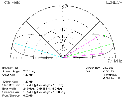
Figure 2 shows the EZNEC comparative gains dBi and radiation patterns. Box 1471 RR1 5697 Concession 6 Everett Ontario Canada L0M 1J0. Note the low angle of radiation.
Even though the low angle radiation may not be any better than a dipole an elongated loop narrows the vertical pattern and can reduce the strength of signals coming in at higher angles making it easier to hear the DX. The feedpoint impedance of the 2 wavelength loop is around 260 ohms at the resonant frequency which is a bit lower than twice the fundamental. Fig 6Example of orientation of loop antenna that does not respond to.
Equivalent to two λ2 vertical dipoles END COUPLED. In this card a double delta. This null is very narrow and is.
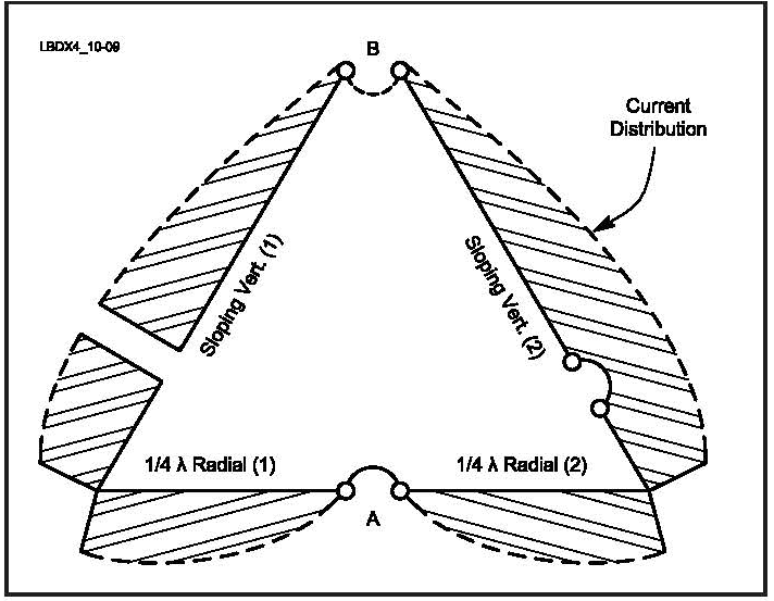
The current at the grounded far end of the vertical element of the half delta loop is 097Z69 A. Generally a magnetic loop will have its highest radiation inline with the vertical elements. Two-dimensional pattern can be obtained from three-dimensional pattern by dividing it into horizontal and vertical planes.
The Delta loop or quad loop effective operating height is really the mean height of current maxima locations. A word of warning. The shape of the vertical pattern is a vertical cross cut of the three-dimensional graph.
The 80 meter Delta Loop is mounted in a vertical plane. Polarization of Loop Antennas HF DX signals are constantly changing in polarization The loop may be vertical or horizontal depending on feed point Vertical polarization is preferred when antenna is low DX rule is to feed the loop for low radiation angle Practical consideration is feed at ground level Select Feed Point to keep. Length ft 1005 f MHz Wanted.
Fig 4Calculated small loop antenna radiation pattern. Often because height is limited deltas are installed in a squashed form. Vertical antenna meaning that vertically polarized loops close to the ground will not work well over poor soil.
Loop curves are solid lines. 30 INSTALLATION INSTRUCTIONS 31 COAXIAL CABLE. Large loop antennas or self-resonant loop antennas have a perimeter close to one wavelength at the operating frequency which makes them self.
I am trying to learn about proper location and mounting. Fig 5Simple untuned small loop antenna. Note that the vertical pattern of a dipole changes radically as height is changed above 14 wavelength or 125 feet on 160 meters or 65 feet on 80 meters.
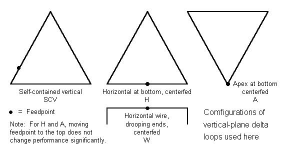
The two above pictures show the radiation pattern of the Delta Loop fed in the bottom corner of the antenna. The Alford loop is mounted on a platform parallel to the ground and it has both a non-directional horizontal pattern and figure-eight pattern. Support Support Loop is fed on the vertical side giving vertical polarisation.
½λ vertical with a loading coil. 4 - Vertical patterns and gains for the loop over the dipole antenna at various heights above perfectly conducting ground. A loop antenna is a radio antenna consisting of a loop or coil of wire tubing or other electrical conductor that is usually fed by a balanced source or feeding a balanced loadWithin this physical description there are two distinct types.
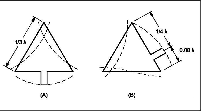
The shape of the vertical pattern is a vertical cross cut of the three-dimensional graph. 025 λ One wavelength Rectangular loop for 21 MHz Tower 10 ft. Copyright 2009 Maple Leaf Communications PO.
A vertical loop makes a good NVIS antenna for the lower bands even if it isnt very high and feeding it at the bottom reduces the required feedline length. The horizontal loop vertical pattern stays relatively constant only decreasing in ground loss as height is increased. Since it is desirable to use the same antenna over a broad frequency band of about ten megahertz it is important that the impedance at the feed point does not vary widely over this band.
At low heights the gain for the loop is low and the radiation angles are high for. See Figs 4B and C. Freespace quad element isotropic referenced gain is 327 dBi.
This is a very realistic situation especially on 80 meters. Fig 10-3 shows both the azimuth and elevation radiation patterns of a vertically polarized quad loop with a top height of 03 λ bottom wire at approximately 004. Would it have the same performance.
Radiation Pattern in 2D. Due to the distance between the antennas and resulting phasing effects the resulting radiation pattern would have an extreme number of lobes. In this card a double delta cross loop antenna is proposed in which two triangular antennas delta loop of different sizes are.
Only the the vertical sides radiate. Vertical plane loops tend to waste more radiation at high angles when they are 2 wavelengths or longer which limits their application as multiband antennas. This configuration is best suited for working long haul DX.
H-plane represents the Horizontal pattern whereas V. Two-dimensional pattern can be obtained from three-dimensional pattern by dividing it into horizontal and vertical planes. Vertical delta loop antenna radiation pattern First publication.
NEVER connect two antennas together through a coupler thinking this would produce better all around coverage. Current User Created Date. With a 70-foot tall support a delta or quad loops antenna elevation pattern is one of much lower actual height.
When horizontally mounted the antenna pattern is omni-directional with nulls straight up and straight down. The base of the Delta Loop is only 10 feet above average ground. Some readers will note that this is close to the same length as the popular 58λ 43 ft vertical for 20m.
February 1991 In the circular polarized antenna with two orthogonal wire antennas of identical shape each antenna is fed with a phase difference of 90 degrees. These resultant patterns are known as Horizontal pattern and Vertical pattern respectively. Thus the quad element has 327 - 213 114 dBd gain over the dipole.
When looking through the loop from the side there is a deep null where the signal can be greatly attenuated. The radiation patterns for different angles of looping are also illustrated clearly in the figure. The antenna in this article at only 23 the height of a full ½λ vertical does just that.
In the most generic terms it appears a horizontal mounting of a magnetic loop should produce a general omnidirectional antenna and a vertical mounting of a magnetic loop should produce a directional antenna. The tangent line at 0 indicates vertical polarization whereas the line with 90 indicates horizontal polarization. The gain of a freespace dipole with typical negligible copper losses is 213 dBi.
I am studying the very basics of magnetic loop antennas I do not have one. The figures show the Omni directional radiation pattern in H and V planes as explained above. Again this is relatively convenient to match.
Whip antennas less than one-half wavelength long including the common quarter wave.
Top Band Hams Vertical Loop Antennas

Delta Loop Antenna Radiation Patterns Hy Power Antenna Company

Delta Loop Antenna Radiation Patterns Hy Power Antenna Company

Delta Loop Antenna Radiation Patterns Hy Power Antenna Company
Delta Loop
Top Band Hams Vertical Loop Antennas

Delta Loop Antenna Radiation Patterns Hy Power Antenna Company
All Band Use Of Vertical Plane Deltas
0 comments
Post a Comment